Using a Thermal Imaging Device
Basic Instructions for using a FLIR T-200 Infrared Thermal Imaging Camera
Safety Warnings
- Wear appropriate personal protective equipment before beginning any inspection procedure.
- Never look directly into the laser beam!
- Charge the battery and install it correctly in the camera.
The battery must be fully charged for the camera to work properly.
The indicator light on the bottom of the camera will be green when the battery is charged. - Insert the memory card into the slot in the top of the camera by lifting the rubber cover that protects the slot and pushing the memory card into the slot until you hear a click.
- Turn the camera on using the on/off button.
This is button number 13 on Diagram A. - Set the temperature range of the object to be scanned.
For most scans this range will be from 100° to 400° on the Fahrenheit scale. - Aim the camera lens toward the inspection point.
- Depress the laser pointer button to turn on the aiming laser.
This is button number 1 on Diagram B. - Place the red laser dot on the inspection point.
Never look directly into the laser beam! - Adjust the lens angle to suit your work position and support the camera with both hands.
- Center the entire inspection point in the viewfinder.
- Press and release the focus button to enable autofocus.
This is button number 3 on Diagram B.
It is important to hold the camera steady during the autofocus process. - Press and hold the preview/ save button for two seconds to preview the image.
This is button number 2 on Diagram B. - Press and release the preview/ save button to save the image.
- Download the image by connecting the camera to a computer with a USB cable and by follow the onscreen instructions.
The cable connection point is located inside the cable connector bay on the bottom of the camera. - Depress the on/off button for two seconds to turn off the camera.
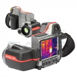
FLIR T-200 Infrared Thermal Imaging Camera
Interpreting the Results of a Thermography Scan
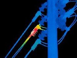
Thermal Image of Wire Overheating
Potential Diagnosis: Wire Shortage
Note the progression of color from left to right as it blends from blue to green to yellow to red. Although the scale is not shown in this scan, the color change indicates an overheating condition. This localized overheated condition at the insulator should be checked for possible connection issues or insulation damage as soon as possible. Perform a follow-up thermal inspection after repairs are made.
Note the progression of color from left to right as it blends from blue to green to yellow to red. Although the scale is not shown in this scan, the color change indicates an overheating condition. This localized overheated condition at the insulator should be checked for possible connection issues or insulation damage as soon as possible. Perform a follow-up thermal inspection after repairs are made.
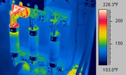
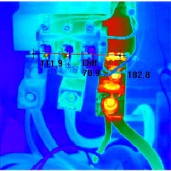
Thermal Image of Loose Connection
Potential Diagnosis: Loose Electrical Connection
Note the two hundred-plus degree temperature at the top of the left-hand fuse. This overheated condition is due to a loose or corroded connection at the junction between the fuse and the fuse holder. The connection should be cleaned and tightened at next scheduled downtime. If pitting is present, the connector should be replaced. Perform a follow-up thermal inspection after repairs have been performed.
Note the two hundred-plus degree temperature at the top of the left-hand fuse. This overheated condition is due to a loose or corroded connection at the junction between the fuse and the fuse holder. The connection should be cleaned and tightened at next scheduled downtime. If pitting is present, the connector should be replaced. Perform a follow-up thermal inspection after repairs have been performed.
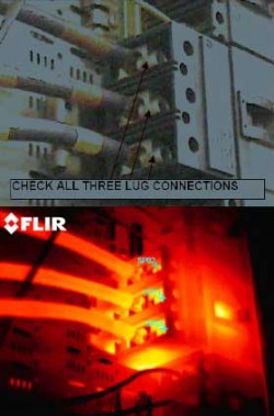
Thermal Image of Overloads Overheating
Potential Diagnosis: Overheating
Note that the entire overload box is overheating. Additionally, all three input leads are hot. This condition could be due to three loose or corroded lug connections, but it is also possible that there could be an overload condition downstream causing an overheating situation. It should be immediately determined if there is a downstream overheating condition, and if so, it should be corrected immediately. If no such condition exists, check, clean, and tighten the three lug connections. Perform a follow-up thermal inspection after the repairs have been completed.
Note that the entire overload box is overheating. Additionally, all three input leads are hot. This condition could be due to three loose or corroded lug connections, but it is also possible that there could be an overload condition downstream causing an overheating situation. It should be immediately determined if there is a downstream overheating condition, and if so, it should be corrected immediately. If no such condition exists, check, clean, and tighten the three lug connections. Perform a follow-up thermal inspection after the repairs have been completed.

Thermal Image of Transformer Overheating
Potential Diagnosis: Bent Cooling Fin
Note the overheated condition at the top center of the middle electrical transformer. Further note how the wire is beginning to overheat at the connector and along the wire itself. It is likely that this transformer is in the beginning stages of a failure mode. Replace the unit as soon as possible. Perform a thermal re-inspection after the new component has been installed.
Note the overheated condition at the top center of the middle electrical transformer. Further note how the wire is beginning to overheat at the connector and along the wire itself. It is likely that this transformer is in the beginning stages of a failure mode. Replace the unit as soon as possible. Perform a thermal re-inspection after the new component has been installed.
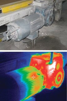
Thermal Image of Gearbox Running Hot
Potential Diagnosis: Lubrication Shortage
Note the overheated condition of the gearbox, which is most likely due to a low level of gear lubricant. Also note that the electric motor is beginning to show signs of overheating. The gearbox lubrication level should be checked and lubricant added as soon as possible. A follow-up thermal inspection should be made to be certain that the gearbox has not suffered permanent damage. A follow-up oil analysis inspection is also indicated in this instance.
Note the overheated condition of the gearbox, which is most likely due to a low level of gear lubricant. Also note that the electric motor is beginning to show signs of overheating. The gearbox lubrication level should be checked and lubricant added as soon as possible. A follow-up thermal inspection should be made to be certain that the gearbox has not suffered permanent damage. A follow-up oil analysis inspection is also indicated in this instance.
Thermal Image of Defective Electrical Contact
Potential Diagnosis: Defective Electrical Contact
Note the overheated condition of the contact on the right. This overheated state may have originally been caused by a loose connection, but now that the contact has been overheated, it should be replaced at the earliest opportunity. A follow-up thermal inspection should be performed after the repairs have been made.
Note the overheated condition of the contact on the right. This overheated state may have originally been caused by a loose connection, but now that the contact has been overheated, it should be replaced at the earliest opportunity. A follow-up thermal inspection should be performed after the repairs have been made.
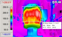
Thermal Image of Electric Motor Running Hot
Potential Diagnosis: Motor Winding Deterioration
Note that the motor windings are heated to a temperature above two hundred degrees. Regardless of the initial cause of this condition, this motor should be now replaced as soon as possible. Perform a follow-up thermal inspection once the replacement has been completed.
Note that the motor windings are heated to a temperature above two hundred degrees. Regardless of the initial cause of this condition, this motor should be now replaced as soon as possible. Perform a follow-up thermal inspection once the replacement has been completed.
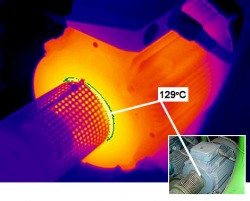
Thermal Image of Misaligned Motor Coupling
Potential Diagnosis: Misaligned Motor Coupling
Note the hot condition associated with the motor coupling. This coupling has slipped, is worn, or is otherwise misaligned. Replace this coupling at the next scheduled downtime. Perform a thermal inspection of the electric motor after the repair has been made.
Note the hot condition associated with the motor coupling. This coupling has slipped, is worn, or is otherwise misaligned. Replace this coupling at the next scheduled downtime. Perform a thermal inspection of the electric motor after the repair has been made.
Images courtesy of Wikimedia Commons.
Last updated 4 May, 2010. Kennesaw State University MAPW. Information for academic purposes only.
Last updated 4 May, 2010. Kennesaw State University MAPW. Information for academic purposes only.
